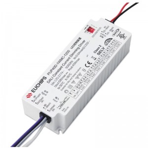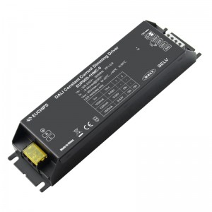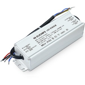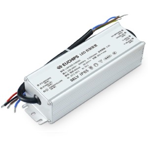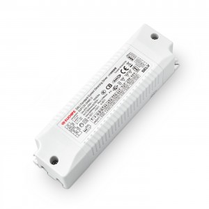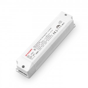
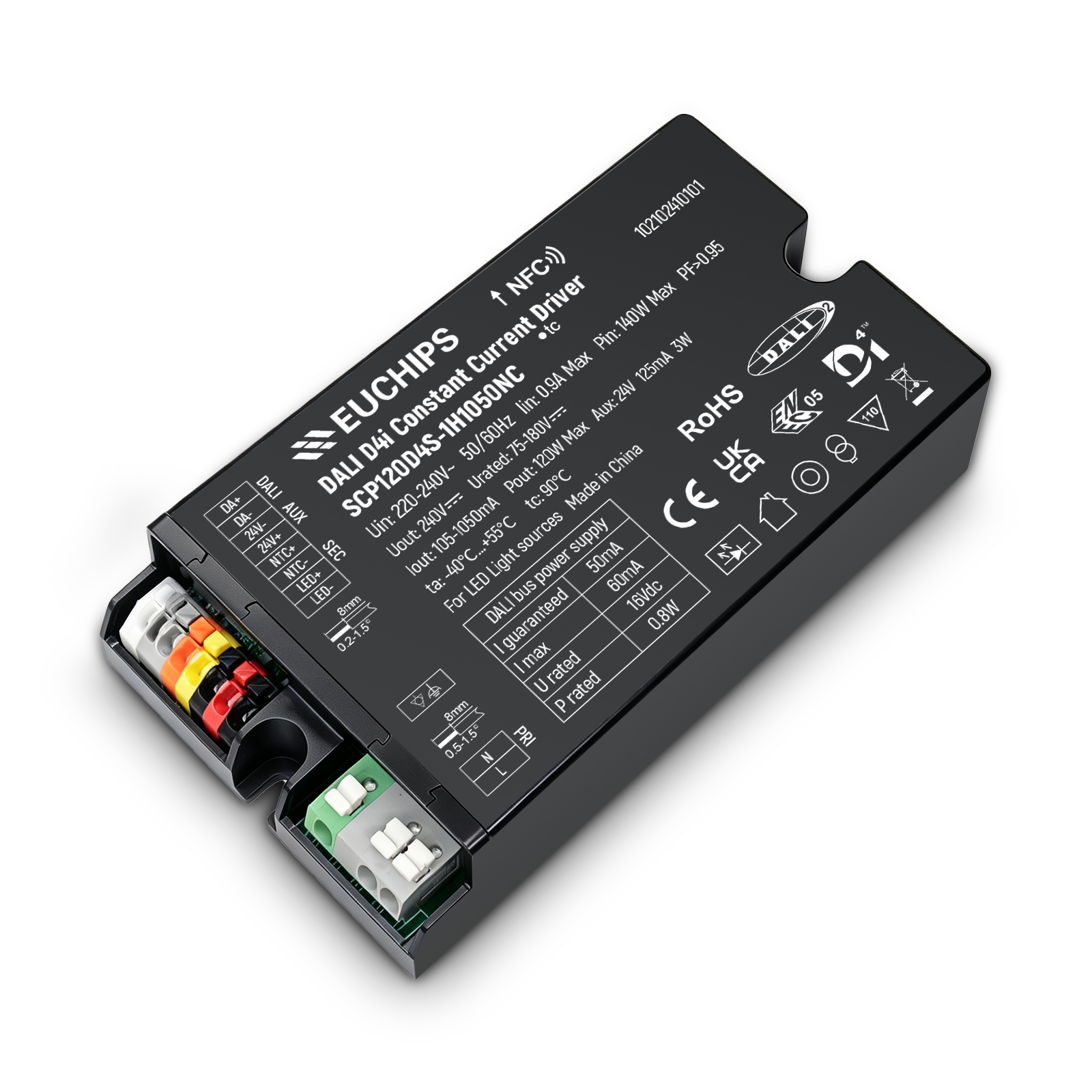
120W D4i CC Driver SCP120D4S-1H1050NC
Features
- Input voltage range: 176-305Vac.
- Constant power design and Constand current mode.
- Adjustable Output Current (AOC) with NFC or DALI-2 programmer.
- AC Dim and 3-modes Timer.
- DALI-2 &D4i Certified(Part 150/250/251/252/253).
- Constant lumen output(CLO).
- Auxiliary power supply: 24V/125mA.
- Integrated 16Vdc Bus power supply based on DALI-2 isolated constant voltage design.
- Stand-by power: < 0.5 W.
- Over temperature protection via external NTC.
- Built-in power metering with ±1% accuracy.
- Suitable for luminaires with protection Class I and II.
- All-around protection: IUVP,SCP,OVP,OTP.
- Input surge protection: Differential mode: 6kV, Common mode: 10kV(Class I).
- Complies with Zhaga interface specification book 13.
- IP20 design for indoor and outdoor applications.
- Suitable for dry / damp / wet locations.
- Warranty: 5–8 years.
Technical Parameters
| Model Number | Rated Input Voltage | Max. Output Power | Output Voltage Range | Output Current Range | Default Current | Efficiency (Typ.) | PF (Typ.) | THD (Typ.) |
| SCP120D4S-1H1050NC | 220-240Vac | 120W | 75-180Vdc | 0.105-1.05A | 0.70A | 92.5% | 0.98 | 5% |
| SCP120D4S-1H1050NC-TD | 184-264Vac | 120W | 75-180Vdc | 0.105-1.05A | 0.70A | 92.5% | 0.98 | 5% |
| SCP110D4S-1H1050NC | 220-240Vac | 110W | 75-158Vdc | 0.105-1.05A | 0.70A | 92.5% | 0.98 | 5% |
| SCP110D4S-1H1050NC-TD | 184-264Vac | 110W | 75-158Vdc | 0.105-1.05A | 0.70A | 92.5% | 0.98 | 5% |
Note:
1.All specifications are measured at 25℃ ambient temperature, input voltage 230Vac, and the typical value tested by full load.
2.TD Version: TEDAS standard
Technical Parameters
|
Model |
SCP120D4S-1H1050NC/-TD | ||||
|
Parameter |
Min. |
Typ. |
Max. |
Remark | |
|
Input |
Rated Input AC Voltage |
220-240Vac |
TD Version: 184-264Vac input | ||
| Input AC Voltage Range |
176Vac |
- |
305Vac |
Reference derating curve | |
| Frequency Range |
47Hz |
50/60Hz |
63Hz |
||
| Input AC Current |
- |
- |
0.90A |
At 176Vac input and 100% load | |
| Input AC Power |
- |
- |
140W |
At 176Vac input and 100% load | |
| Leakage Current |
- |
- |
0.70mA |
IEC 60598-1; 240Vac/ 60Hz, | |
| Inrush Current |
- |
- |
60A |
At 230Vac input and 100% load, 25°C Cold Start | |
| Standby Power |
- |
- |
0.5W |
230Vac&50Hz, Auxiliary Power Without Load and 16Vdc BusPower Supply Shut Off | |
| Power Factor |
0.92 |
0.98 |
- |
At 230Vac , 50-60Hz, 60%-100% load | |
| THD |
- |
5% |
10% |
At 230Vac , 50-60Hz, 60%-100% load | |
|
Parameter |
Min. |
Typ. |
Max. |
Remark | |
|
Output |
Efficiency @220Vac |
91.0% |
92.5% |
- |
At 100% load and the output current is 0.70mA |
| Output Voltage Range |
75V |
- |
180V |
The full power cannot be lower than 115Vdc | |
| Open Circuit Voltage |
- |
- |
240V |
||
| Output Current Range |
0.105A |
- |
1.05A |
The DALI or NFC programmer regulates the current | |
| Current Accuracy |
-5% Iset |
- |
+5% Iset |
At 30%-100% load | |
| Total Output Current Ripple (pk-pk) |
- |
5% |
10% |
20MHz BW, full load& LED load, the ripple would be tiny different under different LED load. | |
| Startup Overshoot Current |
- |
- |
5% |
At 100% load | |
| Line Regulation |
+1% |
- |
+1% |
At 100% load | |
| Load Regulation |
+3% |
- |
+3% |
Input Voltage 230Vac, load changes from 60% to 100%. | |
| Turn-on Delay Time |
- |
1.0s |
1.5s |
At 230Vac input and 100% load | |
| Output PstLM |
- |
- |
0.03 |
In entire operating window | |
| Output SVM |
- |
- |
0.03 |
In entire operating window | |
| Power Monitoring Accuracy |
-1% |
- |
+1% |
Measured at 230Vac input and 100% load | |
| 24V Auxiliary Output Voltage |
21.6V |
24V |
26.4V |
220-240Vac,Power load>0.1W | |
| 24V Auxiliary Output Source Current |
0mA |
- |
125mA |
Return terminal is “24V−/DA-” | |
| 24V Auxiliary Output Transient Peak Current @6W |
- |
- |
250mA |
250mA peak for a maximum duration of 2.2ms in a 6.0ms period during which time the average should not exceed 125mA. | |
| 24V Auxiliary Output Transient Peak Current @10W |
- |
- |
425mA |
425mA peak for a maximum duration of 1.3ms in a 5.2ms period during which time the average should not exceed125mA. | |
| Integrated DALI-2 Bus Power Supply Voltage |
12V |
16V |
20V |
Voltage is depending on loading. | |
| Integrated DALI-2 Bus Power Supply Current |
50mA |
- |
60mA |
Short circuit protection,return terminal is “24V-/DA−” | |
|
DALI-2 |
DALI-2 (High Voltage Level) |
9.5V |
16V |
22.5V |
|
| DALI-2 (Lower Voltage Level) |
-6.5V |
0V |
6.5V |
Return terminal is “DA−” | |
| DALI-2 (Dimming Output Range) |
0%,10% Iset |
- |
100% Iset |
Iset=0.35~1.05A Recommended | |
| DALI-2 (Sink Current) |
- |
- |
2.0mA |
||
Note:
[1]DALI-2 bus power supply is enabled by default and can be disabled via programming interface.
[2]DALI-2 bus power supply supports automatic shut-down and restart after short-circuit.
[3]DALI signal line shall not be connected to the five-core terminal shared by input and dimming.
[4]The DALI signal line shares the negative with the 24V auxiliary source. The 24V auxiliary source can be used alone or share the negative pole with the DALI line.