120W 400~600mA*1ch 0-10V CC Driver ANS120AS-1BMC-OP
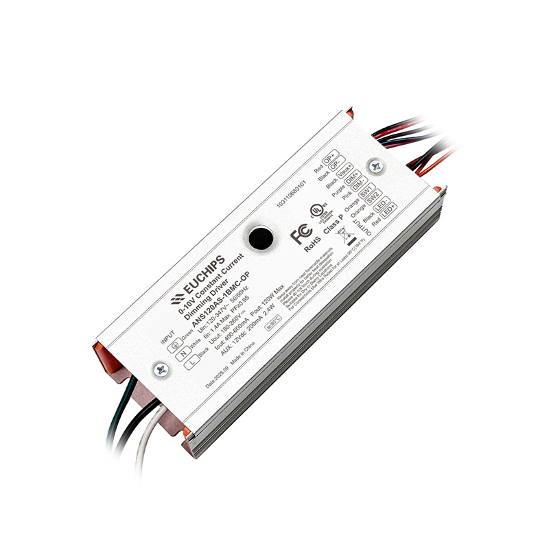
120W 400~600mA*1ch 0-10V CC Driver ANS120AS-1BMC-OP
Features
• Input voltage range: 108-380Vac
• Supports isolated dimming (0-10V active signal, PWM signal, resistor)
• Adjustable Output Current (AOC) with Potentiometer
• High Efficiency up to 96.0%
• Auxiliary Power: 12VDC,200mA
• Support for external DIP switches to adjust power
• Support for external light control switch
• Protection: IUVP,SCP,OVP, OTP
• Input surge protection: Differential mode: 6kV, Common mode: 6kV(ANSI/C82 .77-5-2017)
• 5-year warranty
• Safety according to UL8750
Models
| Model Number | Input Voltage Range |
Max. Output Power |
Output Voltage Range | Output Current Range | Default Current | Efficiency (Typ.) |
PF (Typ.) |
THD (Typ.) |
| ANS120AS-1B* | 108-380Vac |
120W |
180-260Vdc | 0.40-0.60A |
0.55A |
96.0% |
0.98 |
7% |
Note:
[1]. All specifications are measured at 25℃ ambient temperature, input voltage 277Vac, and the typical value tested by full load
[2]. AS means 0-10V/PWM/res dimming and 12V auxiliary source.
* Means Additional Function
| Models |
0-10V/PWM/Res dimming |
Auxiliary 12V/200mA |
DIP switch |
Light control switch |
| ANS120AS-1B |
√ |
√ |
||
| ANS120AS-1BMC |
√ |
√ |
√ |
|
| ANS120AS-1B-OP |
√ |
√ |
√ |
|
| ANS120AS-1BMC-OP |
√ |
√ |
√ |
√ |
Technical Parameters
|
Model |
ANS120AS-1B* | ||||
|
Parameter |
Min. |
Typ. |
Max. |
Remark | |
|
Input |
Rated Input AC Voltage |
120Vac |
- |
347Vac |
|
| Input AC Voltage Range |
108Vac |
- |
380Vac |
Reference derating curve | |
| Frequency Range |
47Hz |
50/60Hz |
63Hz |
||
| Input AC Current |
- |
- |
1.4A | At 120Vac input and 100% load | |
| Input AC Power |
- |
- |
140W |
At 120Vac input and 100% load | |
| Leakage Current |
- |
- |
0.75MIU | UL 8750; 277Vac/ 60Hz | |
|
- |
- |
0.70mA |
IEC 60598-1; 240Vac/ 60Hz, | ||
| Inrush Current |
- |
- |
35A |
At 120Vac input and 100% load, 25�C Cold Start | |
|
- |
- |
70A |
At 277Vac input and 100% load, 25�C Cold Start | ||
|
- |
- |
90A |
At 347Vac input and 100% load, 25�C Cold Start | ||
| Standby Power |
- |
- |
0.5W |
At 220Vac input and Aux. power without load | |
| Power Factor |
0.95 |
0.98 |
- |
At 277Vac , 50-60Hz, 100% load | |
|
0.90 |
- |
- |
At 120-347Vac , 50-60Hz, 70%-100% load | ||
| THD |
- |
7% |
10% |
At 277Vac , 50-60Hz, 100% load | |
|
- |
- |
20% |
At 120-347Vac , 50-60Hz, 70%-100% load | ||
|
Parameter |
Min. |
Typ. |
Max. |
Remark | |
|
Output |
Output Voltage Range |
180V |
- |
260V |
|
| Open Circuit Voltage |
- |
- |
310V |
||
| Output Current Range | 0.40A |
- |
0.60A | Adjustable Output Current with Potentiometer; | |
| Efficiency @120Vac |
92.5% |
94.0% |
- |
At 100% load and Io=0.46A | |
| Efficiency @277Vac |
94.5% |
96.0% |
- |
At 100% load and Io=0.46A | |
| Efficiency @347Vac |
94.5% |
96.0% |
- |
At 100% load and Io=0.46A | |
| Output Current Tolerance |
-5% |
- |
+5% |
At 100% load | |
| Output Current Ripple(PK-AV) |
- |
5% |
10% |
At 100% load, 20 MHz BW | |
| Startup Overshoot Current |
- |
- |
10% |
At 100% load | |
| Turn-on Delay Time |
- |
- |
1.0s |
At 120~347Vac input and 100% load | |
| Line Regulation |
-5% |
- |
+5% |
At 25℃ ambient temperature, input voltage changesfrom 120Vac to 347Vac. | |
| Load Regulation |
-5% |
- |
+5% |
At 25℃ ambient temperature, Input Voltage 240Vac, load changes from 70% to 100%. | |
| 12V Auxiliary Output Voltage |
10.8V |
12V |
13.2V |
||
| 12V Auxiliary Output Current |
- |
- |
200mA |
Return terminal is “Dim�“ | |
|
Parameter |
Min. |
Typ. |
Max. |
Remark |
|
|
0-10V Dimming |
Absolute Maximum Voltage |
0V |
- |
12V |
On Dim+ Pin |
| Source Current on Dim+ Pin |
90uA |
110uA |
120uA |
||
| Dimming Output Range |
10%Ioset |
- |
100%Ioset |
Ioset<0.46A, Dimming Min. is 0.046A | |
| Recommended Dimming Range for 0-10V |
0V |
- |
10V |
Dimming prohibits reverse connection | |
| Dim Off | 0.7V | 0.8V |
0.9V |
With afterglow (standard) Without afterglow (optional) | |
| Dim On |
0.9V |
1.0V |
1.1V |
||
| PWM Dimming | PWM_in High Level |
9.8V |
10V |
10.2V |
|
| PWM_in Low Level |
0V |
- |
0.3V | ||
| PWM_in Frequency Range |
1KHz |
- |
2KHz |
||
| PWM_in Duty Cycle |
0% |
- |
100% |
||
| Resistor Dimming | Resistance |
0Kohm |
- |
100Kohm |
DIM+ source current 110uA. |
| Dimming Output Range |
10%Ioset |
- |
100%Ioset |
||
|
Other Characteristics |
Operating TemperatureFor safety(Tc) |
-40℃ |
25℃ |
+90℃ |
|
| Operating TemperatureFor warranty(Tc) |
-40℃ |
25℃ |
+85℃ |
Case temperature for 5 years warranty Humidity: 10%RH to 95% RH; | |
| Storage Temperature(Ta) |
-40℃ |
25℃ |
+85℃ |
||
| Storage Humidity |
5%RH |
- |
95%RH |
||
| Altitude |
-65m |
- |
4000m |
||
| Temperature Coefficient |
-0.06%/℃ |
- |
+0.06%/℃ |
Tc:0 ℃~90℃ | |
| Input under voltage protection |
- |
85Vac |
100Vac |
Self-recovery | |
| Over temperature protection |
90℃ |
95℃ |
100℃ |
Drop current when OTP, and it can be self-recoveryafter the abnormality is removed. | |
| Short Circuit Protection |
- |
- |
- |
Self-recovery, short circuit without damage | |
| Lifetime(Tc≤90℃) |
≥50,000 hours |
At 100% load,please refer to lifetime vs. casetemperature curve | |||
| MTBF |
200, 000 hours |
At 220Vac,80% load,Ta=25 ℃ (MIL-HDBK-217F) | |||
| Warranty |
5 years |
Tc ≤90℃ | |||
| Net Weight |
420g |
||||
| Dimension |
138mm*52.5mm*33.5mm |
Lx W x H | |||
Note: All the parameters above are tested Ta 25℃ and LED load, unless specified.
Safety and EMI/EMS Standards
| Safety Certification | Standard |
Status |
Remark |
| UL/cUL | UL8750, CSA C22.2 No.250.13 |
√ |
|
| CB | IEC61347-1, IEC61347-2-13 | ||
| CE | EN 61347-1, EN 61347-2-13, EN62493 | ||
| ENEC | EN 61347-1, EN 61347-2-13, EN IEC 62384 | ||
| CCC | GB/T 19510.213, GB/T 19510.1 | ||
| SAA | AS/NZS 61347.1,AS/NZS61347.2.13 | ||
| BIS | lS15885:2012 Part 2 Sec 13 |
| EMC Category | Standard |
Status |
Remark |
| FCC | FCC Part15: Subpart A ANSI 63.4:2014 |
√ |
|
| CE | EN 55015, EN 61000-3-2, EN 61000-3-3, EN 61547 | ||
| CE | EN61000-4-2,3,4,5,6,11 | ||
| Surge | ANSI/C82 .77-5-2017 | Criterion B | |
| Ring Wave | ANSI/C82 .77-5-2017 | Criterion B |
Safety Test Items:
| Safety Test Items | Technical Indicators | Remark | |
| Insulation Requirements | UL Insulation Requirements | CE/ENEC Insulation Requirements | |
| Input-Case | 2U+1000Vac |
/ |
Basic insulation |
| Input-Dim | 2U+1000Vac |
/ |
Reinforced insulation |
| Dim-Case | 500Vac |
/ |
Basic insulation |
| Insulation Resistance | ≥10MΩ | Input-Dim,Test voltage:500Vdc | |
| Ground Resistance | ≤0. 1Ω | 25A/1min | |
Note:
1. LED Driver itself complies with EMC standard. However, LED Driver ’s EMC should be re-checked when integrated into lighting systems due to unexpected interference of components.
2.Please short L and N, LED+ and LED-, Dim+ and Dim - and Vaux+ and Vaux- when Hi-pot test.